3D Modeling - Exercises
24.4.2024 - / Week 1 - Week
Chan Wan Qing / 0350928 / BA of
Design (HONS) in Creative Media
3D Modeling
Exercises
INDEX:
1.
Lectures
2.
Exercises
Exercise 1: Primitive Modeling
Exercise 2: Cylindrical Modeling
Exercise 3: Box Modeling
Exercise 4: Organic Modeling
3.
Feedbacks
4.
Reflection
LECTURES
Week 1 / 24.4.2024
We were introduced to the module, 3D modelling about its role in this industry. After that, we were briefed about the exercises and projects for this module. As next week is a public holiday, Mr Kamal tried to cover next week's lecture in today's class.
https://miro.com/app/board/uXjVKQXpyOQ=/
3D Animation
Pre-production > Production > Post Production
Pre-production: Visual materials, storyboard, character design
Production: 3D Modelling, texturing, rigging, animating (12 animation principles), lighting, rendering (process, still image/sequences)
Post Production: Composition, editing, colour grading, audio

Fig.1.2 UV/Unwrap/Texturing (Sketch Notes)
After the briefing session, we proceeded to the first lesson, which is blender introduction syllabus.
Rotate: MMB (Hold + Drag)
Track / Pan: Shift + MMB
Zoom: MMB
(Scroll / Ctrl + MMB)
3D Viewpoint
Single to Quad View (Top, Front, Right,
Perspective): Ctrl + Alt + Q
Duplicate: Shift + D
In-class Exercise
In the class, we were required to create a table using what we had learnt. Mr Kamal first demonstrated to us step by step. We started by using cube and changed its scales to transform it to a rectangular as the legs of the table. Then we duplicated it and changed its location values to create 4 legs of the table. Then, we created another cube and made it thinner as the top surface of the table.
Week 3 / 8.5.2024
In week 3, we are going to learn about the topic, polygonal modeling, focusing in cylindrical modeling.
https://miro.com/app/board/uXjVKK7GaWI=/
Blender 3.6 - Edit mode
TAB: Switching object mode and edit mode
1: Vertex; 2: Edge; 3: Face
I:
Inset
E: Extrude
Ctrl + R: Loop cut
S: Scale up / Scale
down
In the class, we did an exercise to create a bottle using a blue print. We used the skills that we learned in the class in this exercise.

Fig.1.10 Low Poly Bottle Model
*Adjust mean crease

Fig.1.11 High Poly Bottle Model
Week 4 / 15.5.2024
In week 4, we are going to build a box model.
In-class Exercise
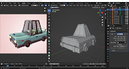
Following the blueprint, we started to build the cartoon car model in Blender.
With the tools we previously learned, we built the cartoon car model starting from its body. For this exercise, we built a low poly model. Most of the tool we used are what we have learnt in the previous weeks.
*Delete Half > Add Modifier > Mirror
*Select > Material >
Add > Assign [Colour]
Week 6 / 29.5.2024
In week 6, we did a karambit model with the blueprint provided.
We learned to use bool tool, where we use different options including differences, union, intersect and slice to alter the combining model of 2 shapes.
Bool tool: Ctrl + Shift + B
Edge > Bridge Edge Loops
Select both edges and press F: Faces
INSTRUCTIONS
Exercise 1: Primitive Modeling
For the first exercise, we are required to think of an object that can be simplified as a combination of primitive shapes and sketch it out for inspiration. After that, we need to use Blender to model the objects using primitive objects such as sphere, cylinder, cube, cone, etc. We may use transformation tools to manipulate the object and modifier tools to deform the model.
Requirements:
- Output size: 720p (1280 x 720)
- Format: .png (render final image using Viewport Render Image)
- Final render solid without wireframe
- Final render solid with wireframe
Submission 2:
- e-portfolio blog link (format *.doc)
- Blender file
First, I tried to find some references of 3d models from Pinterest. There are many different examples of different objects, however some of them is too complex.
During the process, I listed down a few ideas and shortlisted them to do sketching. Ideas: LP Player, Gaming Device, Refrigerator, Camera and Cannon. I did more searching for the designs of the objects above before sketching.
Sketch
I started to sketch out the ideas following what I had researched. Sketching helps me generate more ideas and gain a better understanding of the shapes I should use to construct the object, as well as how to assemble them effectively. As it is a rough sketch, so the proportions of the objects does not look so good.
During sketching, I had some concerns regarding certain ideas, like creating the model of a refrigerator, I'm unsure how to create the internal space and incorporate shelves or compartments effectively within the cube shape. So, I decided to shortlisted the ideas while constructing the models.
Blender
Idea 1: LP Player
In the first week, we were required to start sketching and constructing the model. Then, Mr Kamal will give us his feedbacks to improve on our work and teach us how to render the image in the next class. I started to construct the first idea, LP Player. [Fig2.4-1] First, I started with the base, a cube. I adjust the size by changing the scale values. I kept the scale values of X and Y same as it should a square for the top surface. Then, I added a cylinder on top of the cuboid. [Fig.2.4-2] Similarly, I adjusted the scale to amend the size of the cylinder. After that, I added the smaller parts, as shown in the 3rd to the 5th images in Fig.2.4.
.png)
Fig.2.5 3D Model - LP Player (Quad View)
For the second idea, I constructed a cannon. [Fig.2.6] Based on the sketch, I first started with a rectangular base. Then followed by the wheels beside the base. I added the wheels like how we did the in-class exercise of a table.
Then, I started to construct the cannon part, [Fig.2.7] I added a cylinder and adjusted the size and rotate it as it supposed to be in a inclined position. [Fig.2.8] After adding the first cylinder, I duplicated it subsequently while decreasing the sizes until the whole cannon is formed.
I also added some details in the wheels to make it more realistic.
.png)
Fig.2.10 3D Model - Cannon (Quad View)
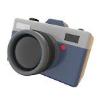
Lastly, I also came out with a camera. However, I was dissatisfied by the result since it did not come out as what I imagined. Similarly, I started with the body as a rectangular, and added the different parts including the lens, flash light, button and more. I felt like the forms are not combining well with each other, so I thought to give up on this idea.
I decided to use the first idea, which is the LP Player as my final exercise 1 as it looks the most realistic out of these 3 ideas. In week 3, we learned to coloured and render the preview image. So, I coloured the object and render the preview image.
Final Exercise 1: Primitive Modeling
Exercise 2: Cylindrical Modeling
In this exercise, we need to think of any object made of cylindrical shape such as a plate, bottle, bowl, glass etc. Then, we have to make a composition from multiple different objects. We can find as much as references such as blueprint or images for selected objects while constructing the model in Blender. Then, we can start to model the object using a primitive cylinder by utilising modeling tools like extrude, bevel, inset and loop cut. After that, apply a smooth modifier and adjust the sharpness or smoothness of the corner using various techniques.
Requirements:
- Output size: 720p (1280 x 720)
- Format: .png (render final image using Viewport Render Image)
- Final render solid without wireframe
- Final render solid with wireframe
Submission 2:
- e-portfolio blog link (format *.doc)
- Blender file
References
Blender
Following what we did in week 3's classes for in-class exercise, I started with adding the blue print image into Blender as references. I first construct the model of a glass. I followed the second image of glasses in [Fig.2.15] and add cylindrical shape. Starting from adjusting the size of the base, I then use inset to decrease the size and use extrude to create the holding part of the glass. Then, I construct the upper part with extrude and scale in. After completing the rough shape of the glass, I added loop cut on the curve part and use bevel for the curvature parts. I then apply smooth modifier to the glass after the shape of the model is similar to the reference.
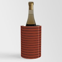
The second thing I constructed is a wine bucket. Similarly, I add the image as references and start with cylindrical shape and use extrude tool to extend the shape. Like what we learned in week 3, I used loop cut to create some patterns on the bucket. After completing the shape, I apply smoothness on the bucket and adjusted its value until it looks natural.

Fig.2.20 Glass & Bucket Models
Lastly, I build the model of a wine bottle. I used the blueprint of the wine bottle as reference and started with cylindrical shape. Following the blueprint, I adjusted the height, width and so on. I used extrude and scale in/out while constructing the shape. Then, I used loop cut and bevel tool to adjust the shape to create the curves of the wine bottle. Similar to the previous model, I added smoothness to the model and convert it into high poly.
After completing 3 models, I adjusted their places and started to place them according to composition. I duplicate a wine bottle and a glass and put one of the wine bottles into the wine bucket. I tried to play around with the placements to find the best composition. I added a plane as the base.
I converted them into high poly models and added colours to the models and adjusted the metallic and roughness value. As the wine bottle and wine glasses are made out of glass, I lowered the roughness and for wine glasses, I also lowered the opacity. For the wine bucket, I increase the metallic value as it is made of metal. Then, I added shadow, highlights and more to the models before rendering them.
I amended some of the parts that I found unnatural after looking closely. For example, the bottom part of the wine glasses, the curves are not smooth enough, so I used scale and bevel tool to amend them.
Final Exercise 2: Cylindrical Modeling
.png)
Fig.2.28 Final Cylindrical Modeling (Wireframe)
Exercise 3: Box Modeling
Requirements:
- Output size: 720p (1280 x 720)
- Format: .png (render final image using Viewport Render Image)
- Final render solid without wireframe
- Final render solid with wireframe
Submission 2:
- e-portfolio blog link (format *.doc)
- Blender file
In week 4's class, we did an in-class exercise of a low poly car. So for this exercise, I tried to avoid building a car. I found some references of other types of vehicles or furniture on Pinterest. I could only find a few furniture that are made of box shape, so I focused more on finding vehicles. I found references for bus, forklift and bulldozer.
Blender
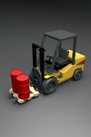
I chose to build a forklift because it is more interesting. In Blender, I started with a cube, and extend the shape. Then, I used loop cut to divide the cuboid. With the tools extrude and scale in and out, I made the body of the forklift according to the reference. In the first attempt [Fig.2.30], it did not go as what I thought especially the body part near the wheel. So, I redo the whole thing from a cube.
In the second attempt, I directly extended and extruded (with loop cut) and
built the body part without the curved section for the wheels, resulting in
a better outcome.
[Fig.2.33] After building the body part, I proceeded to build the roof part of the forklift. I used different tools we learned to build a dashboard first as the front polls are extended from the dashboard. I extended the polls from the dominant cube. But for the roof, I added another cube shape and put it on top after adjusting the size.

[Fig.2.34] Then, I started to build the front part, which is the lifting part. I extended the shape from the dominant model with loop cut and extrude. There are quite a few things in the front part. Here, after extruding the shapes, I also used bevel tool for some parts as they are curved. I also added the planks in front by adding shapes just like the references as they are seperated from the forklift.
[Fig.2.35] Then, I built the wheels like how we did in the in-class exercise. [Fig.2.36] I added a seat seperately and move it into the forklift.
[Fig.2.37] Then, I also added the oil tanks in front just like the reference. I used cylinder as the base shape, and used loop cut and extrude it.
After completing the model, I added colours on the forklift. Like what we learnt in week 4, I applied different colours on different parts.
Final Exercise 3: Box Modeling

Fig.2.40 Final Box Modeling - Forklift
Revised Exercise 3: Box Modeling
After getting feedbacks on Week 6, I changed the angle of the final model.
Exercise 4: Organic Modeling
For exercise 4, we had to download the karambit image as blueprint and model it using organic modeling techniques and tools that we have learnt previously in class. We should apply basic material and colour at the end.Requirements:
- Output size: 720p (1280 x 720)
- Format: .png (render final image using Viewport Render Image)
- Final render solid without wireframe
- Final render solid with wireframe
Submission 2:
- e-portfolio blog link (format *.doc)
- Blender file
For this exercise, we first did it in the tutorial class following Mr Kamal's instructions. However, in class while making the karambit for the first attempt, I couldn't really follow up and model the karambit nicely. So, after class, I watched the recording and attempted a few times to model the karambit.
In the second attempt, the sharp part seems to be to sharp and the surface looks weird after adding a subdivision surface modifier. The side of the blade of the karambit is not smooth too. So, I decided to make another attempt.
In attempt 3, I added a cylinder and used inset method to create the finger ring part. Then following what we did in the class in week 6, I constructed the handle part and joined them together with bridge edge tool. This time, I started with the lower part near the blade because for the last few times, the blade always seems to be crooked.
Then I started to extrude the blade part and scale in each time I extruded. Then, I loop cut horizontally and selected the side of the blade and extrude them along normal. Next, I reduce the thickness of the side of the blade. Last, I extended the tip of the blade following the blueprint.
.png)
Fig.2.47 Karambit (Subdivision: 0)
Then, I used loop cup for the edge of the karambit to reduce the smoothness of the edges where they shouldn't be 'rounded'.
Exercise 4: Organic Modeling - Karambit (Attempt 3)

Fig.2.49 Exercise 4: Organic Modeling
Final Exercise 4: Organic Modeling
After receiving feedbacks in week 7, I add more subdivision on the blade part and amend the handle part by extruding it.
Revised Exercise 4: Organic Modeling
FEEDBACKS
Week 6 / Exercise 3
Specific Feedbacks:
Can have a better camera angle, probably eye level and increase the cavity (ridge and valley). Make sure the plane cover all the object.
Week 7 / Exercise 4
Specific Feedbacks:
Only the tip of the blade needs more division so that it looks smoother, the wireframe looks ok, the other parts are ok.
REFLECTION
Exercise 1: Primitive Modeling
The first exercise is not a very difficult task, it basically allows us to get use to Blender and creating objects with the various shapes. In this task, sketching is very important as through sketching, I am able to understand how are the structures of the objects, and what shapes should I use in order to create the models.
Exercise 2: Cylindrical Modeling
For the second exercise, we were required to use the tools we learned in week 3 to create a few different cylindrical models. Since we had learned more tools and skills, it is more easier for me to alter the shapes into different shapes with bevel, scale in/out, extrude, inset and so on. The shapes are not as limited as in exercise 1, where we can only change the sizes and construct them together. In this exercise, I used bevel tool and scale in/out more as I needed to create curves on the objects. So, my skills definitely increase compared to when I was doing exercise 1. However, it takes me some time to change the colours as I felt like the colours are quite dark, and it is hard for me to determine the final colours. Nevertheless, I am quite satisfied with the final outcome.
Exercise 3: Box Modeling
In the third exercise, we need to build a model using only 1 dominant cube for the main body of the object that is made of box shape. In the beginning, I found different references online as I could only think of building a car, where we did it in week 4's class. While doing research, I tried to find different types of vehicles. I found a few but chose forklift since I thought the reference pic is quite interesting. Initially, I was quite frustrating while constructing the main body, because it doesn't not really come out like the reference pic, so I restart a few times while recalling how we did the exercise in the class. At last, I was able to figure out. While constructing the model, I used loop cut and extrude tools the most since we started with only 1 cube. After building the main body, I slowly getting familiar with the tools, and it was a quite smooth process since then. But still, I need some other shapes to add details on the forklift, such as cylinder for the wheels, steering wheel and oil tanks, cube for the plank, the roof, car lights at the back and the seat. Other than those, everything is built from 1 dominant cube. This exercise allows me to be more familiar on using the tools in Blender while learning to construct different shapes from 1 cube. I was really satisfied with the result especially after adding colours.
Exercise 4: Organic Modeling
.png)


.png)


.png)
.png)
.png)
.png)
.png)
.png)

.png)


.png)


.png)

.png)


.png)
.png)
.png)
.png)

.png)


Comments
Post a Comment